Root Locus Theory - An Important Theory In Control Engineering.

Feb 14, 2019 • 382 views
Introduction :
In control theory and stability theory, root locus analysis is a graphical method for examining how the roots of a system change with variation of a certain system parameter, commonly a gain within a feedback system. This is a technique used as a stability criterion in the field of classical control theory developed by Walter R. Evans which can determine stability of the system. The root locus plots the poles of the closed loop transfer function in the complexs- plane as a function of a gain parameter (see pole–zero plot).
A graphical method that uses a special protractor called a "Spirule" was once used to determine angles and draw the root loci.
Root Locus Theory :
The root locus of a feedback system is the graphical representation in the complexs-plane of the possible locations of its closed-loop poles for varying values of a certain system parameter. The points that are part of the root locus satisfy the angle condition. The value of the parameter for a certain point of the root locus can be obtained using the magnitude condition. Suppose there is a feedback system with input signal X(s) and output signal Y(s). The forward path transfer function G(s) is the feedback path transfer function is H(s).
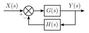
Thus, the closed-loop poles of the closed-loop transfer function are the roots of the characteristic equation 1+G(s) H(s) =0. The roots of this equation may be found wherever G(s)*H(s) = -1.
The factoring of K and the use of simple monomials means the evaluation of the rational polynomial can be done with vector techniques that add or subtract angles and multiply or divide magnitudes. The vector formulation arises from the fact that each monomial term
(S-a) in the factored G(s)H(s) represents the vector from (a) to (s) in the s-plane. The polynomial can be evaluated by considering the magnitudes and angles of each of these vectors.
According to vector mathematics, the angle of the result of the rational polynomial is the sum of zeros need be considered. This is known as the angle condition.
Similarly, the magnitude of the result of the rational polynomial is the product of all the magnitudes in the numerator divided by the product of all the magnitudes in the denominator. It turns out that the calculation of the magnitude is not needed to determine if a point in the s- plane is part of the root locus because K varies and can take an arbitrary real value. For each point of the root locus a value of K can be calculated. This is known as the magnitude condition.
The root locus only gives the location of closed loop poles as the gain K is varied. The value
of K does not affect the location of the zeros. The open-loop zeros are the same as the closed- loop zeros.
Sketching for Root Locus :
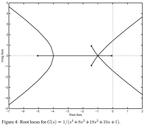
Using a few basic rules, the root locus method can plot the overall shape of the path (locus) traversed by the roots as the value of K varies. The plot of the root locus then gives an idea of the stability and dynamics of this feedback system for different values of K. The rules are the following:
Mark open-loop poles and zeros
Mark real axis portion to the left of an odd number of poles and zeros
Find asymptotes
LetPbe the number of poles andZbe the number of zeros :
P-Z = No. of asymptotes
Where∑pis the sum of all the locations of the poles, and∑zis the sum of all the locations of the explicit zeros.
Phase condition on test point to find angle of departure
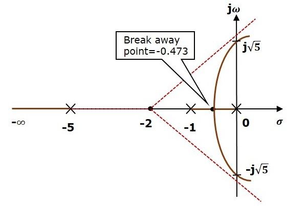
Compute breakaway/break-in points
Once you solve forz, the real roots give you the breakaway/re-entry points. Complex roots correspond to a lack of breakaway/re-entry.
In addition to determining the stability of the system, the root locus can be used to design
the damping ratio (ζ) and natural frequency (ωn) of a feedback system. Lines of constant natural frequency can be drawn radially from the origin and lines of constant damping ratio can be drawn as arccosine whose center points coincide with the origin.
By selecting a point along the root locus that coincides with a desired damping ratio and natural frequency, a gainKcan be calculated and implemented in the controller. More elaborate techniques of controller design using the root locus are available in most control textbooks: for instance, lag, lead, PI, PD and PID controllers can be designed approximately with this technique.
The definition of the damping ratio and natural frequency presumes that the overall feedback system is well approximated by a second order system; i.e. the system has a dominant pair of poles. This is often not the case, so it is good practice to simulate the final design to check if the project goals are satisfied.
Recommended

Kasam Ki Kasam Chords - A.R.Rahman & Shaan - Kabhi Khushi Kabhi Gham
Mera Yaar Chords - Javed Bashir & Shankar Ehsaan - Bhaag Milkha Bhaag